
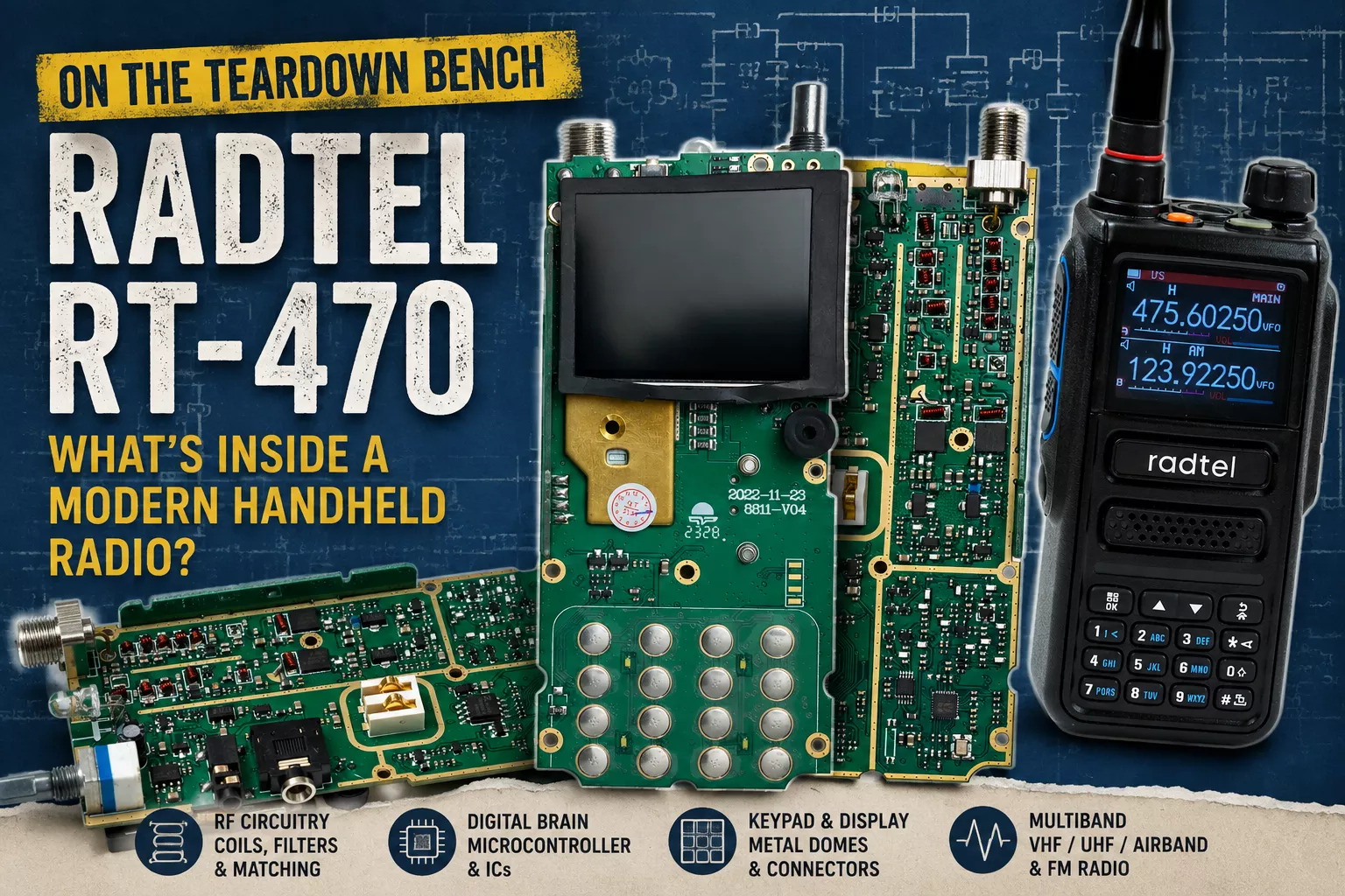
This time, the device on the teardown bench is not broken. My Radtel RT-470 is fully functional and gets regular use; it simply needed a thorough cleaning. For that reason, I did not take it apart any further than what you can see in the photographs. Even so, there is plenty to discover about how nearly all the electronics of a modern handheld transceiver can fit onto a single palm-sized printed circuit board.
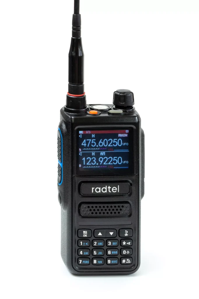
The RT-470 is a multiband, 10-watt handheld radio. In addition to conventional VHF/UHF operation, it can receive AM airband transmissions from 108 to 136 MHz and broadcast FM from 66 to 108 MHz.
Two Sides, Two Worlds
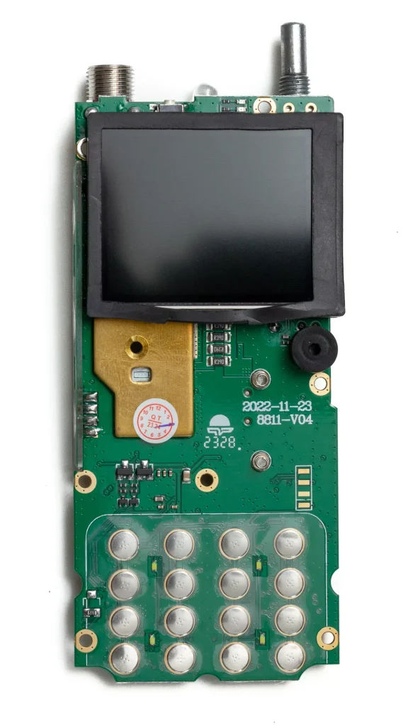
At first glance, the front side of the PCB is almost disappointingly uneventful. The colour display sits at the top, with the keypad below it. The keys do not use individual microswitches: metal dome contacts mounted on the PCB close the circuits when pressed, with the rubber keypad fitted over them. It is a simple, inexpensive solution and particularly well suited to a handheld radio.
The PCB is clearly marked with the date 2023-11-23 and the designation 8811-V04. This places it among the newer generations of RT-470 boards. Radtel provides separate firmware for the old and new PCB versions and specifically warns that firmware intended for one hardware revision should not be used on the other.
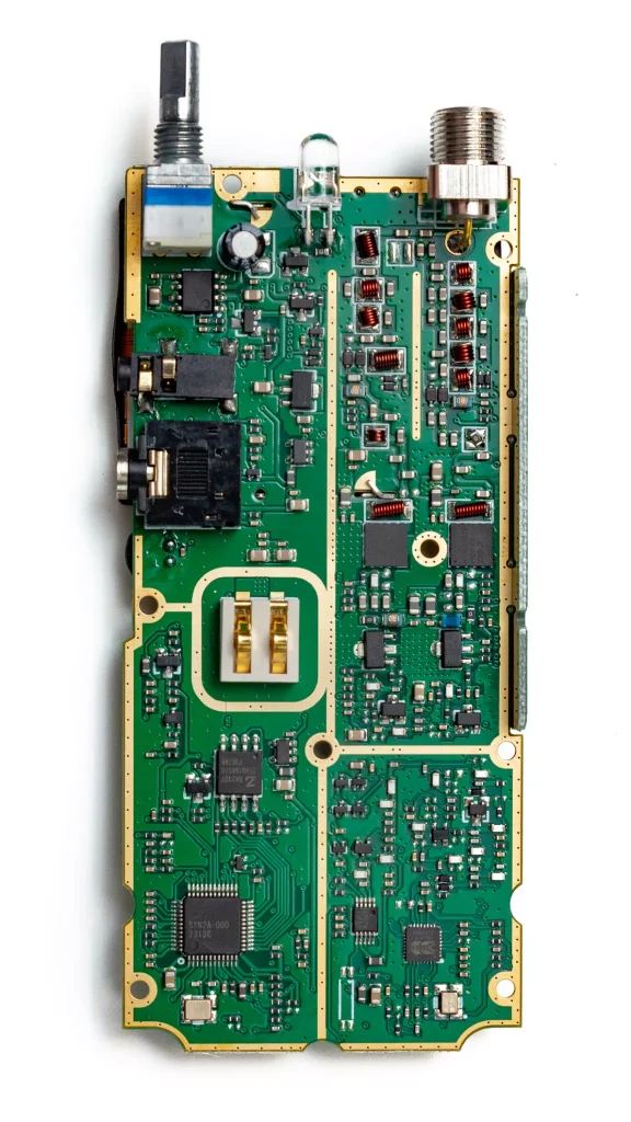
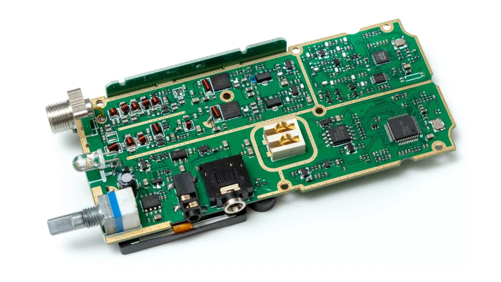
The other side of the board is much more interesting. Around the antenna connector, the first things to catch the eye are the numerous air-core inductors wound from enamelled copper wire. They are not there for decoration: together with capacitors, they form tuning, matching and filtering networks.
It is also worth noting that there is no single universal RF path between the antenna and the rest of the circuitry. Several RF sections run alongside one another, separated by wide grounded copper areas and numerous plated-through vias. This is the classic via fence arrangement: the many ground-connected vias reduce RF coupling and provide better electromagnetic isolation between the different stages of the RF circuitry. In a multiband radio, it is particularly important to filter unwanted harmonics from the transmitted signal while also presenting the final transistor with an acceptable load across the various operating bands.
Below the filters are two larger power semiconductor sections. Around them are wider copper traces, inductors and several relatively large SMD components. This is the territory of the transmitter power amplifier and its matching network.
There is an interesting contrast here. From the outside, the radio looks like a software-controlled digital gadget. Around the antenna, however, we still find essentially the same fundamental components that radio designers relied on decades ago: transistors, coils, capacitors and carefully designed impedance-matching networks.
The Radio’s “Computer”
The lower part of the PCB is dominated by the control electronics. The largest multi-pin IC is clearly marked SYN2A-000. It is one of the radio’s central control devices, surrounded by a dense network of digital traces running to the display, keypad and other sections of the radio.
Next to it is another, smaller QFN package with its own crystal. Its marking cannot be read reliably enough from the photograph to identify it with confidence, but the surrounding circuitry demonstrates just how highly integrated a modern handheld radio has become. Many functions that once required separate mixers, oscillators, demodulators and audio-frequency circuits can now be concentrated into just a handful of ICs.
The digital and RF sections are also clearly separated. The microcontroller, display data traffic and switching power-supply circuits can generate considerable broadband electrical noise. Feeding that noise into the input of a sensitive radio receiver only a few centimetres away would obviously be undesirable.
Familiar Connectors
Along the side of the PCB is the familiar pair of stacked jack sockets commonly found on handheld radios. These provide connections for an external microphone and speaker, as well as for a programming cable. At the top are the antenna connector, the volume/power control mechanism and the large LED.
In the centre of the rear side, spring contacts connect the PCB to the battery. There are no internal wires or separate wiring harnesses: wherever possible, the manufacturer has mounted everything directly onto the main board. This makes the radio cheaper, more compact and easier to assemble and service.
No Need to Remove Every Shield
For a full teardown, of course, the shielding could be removed, the display desoldered and the ICs identified one by one. In this case, I saw little reason to go that far. This is not a donor unit or a broken radio waiting to be repaired. It is a piece of equipment I actually use.
For cleaning, it only needed to be disassembled far enough to expose both sides of the main PCB. And perhaps that is the most interesting thing about it: inside a modern, inexpensive handheld radio, highly integrated digital electronics coexist with very traditional RF engineering. Behind the menus, colour display and firmware, it is still coils, capacitors, transistors and copper tracks only a few millimetres wide near the antenna that ultimately determine what kind of radio it really is.
Firmware, incidentally, is not a trivial detail on this model. Radtel’s official download page treats the old and new RT-470 PCBs separately. The newer hardware uses the 2.x firmware branch, and a later version added support for the 8.33 kHz channel spacing used in the airband. Before updating the firmware, it is therefore worth checking twice exactly which PCB revision is inside the radio.